|
|
| MOQ: | 1 Piece (sample order accepted) |
| Price: | Negotiable |
| Standard Packaging: | Anti-static bag with shock-proof foam, export-grade corrugated carton |
| Delivery Period: | 15-25 working days after sample approval |
| Payment Method: | T/T,L/C,D/P |
| Supply Capacity: | 10000 Pieces per Month |
Technical Dossier / TXW500276I0-TD / 2026
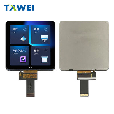
A 5.08-inch, 720 by 720 IPS panel with in-cell touch, four-lane MIPI and a bonded stack of 3.05 mm — built for instruments where the screen is the dial, not a window inside it.
Most square displays are chosen for symmetry and then paid for in compromise. The pixels are stretched into a rectangle and corrected in firmware, the touch layer is bonded on top as an afterthought, and the interface asks for so many conductors that the flex becomes the thickest part of the assembly. A designer then discovers, somewhere around the third enclosure revision, that the screen which looked symmetrical on the mood board has quietly turned into the component that dictates the wall thickness, the gasket line and the clearance behind the front panel. This module was approached from the opposite direction — the sensor sits inside the LCD cell, the matrix is genuinely square at 720 by 720, and a four-lane MIPI link carries everything across a single 30-pin tail.
With the cover glass bonded, the whole assembly measures 3.05 millimetres. That number is not a marketing flourish; it is the difference between a product that can use a snap-fit bezel and one that needs screws, between a front panel that sits flush with the housing and one that stands proud of it. In a category where the display is usually the first component to be compromised, this is a rare case of the geometry arriving before the enclosure drawing rather than after it.
A 91.368 by 91.368 millimetre active area at a 0.1269 millimetre pitch means a circle drawn anywhere on this panel is a circle — not an ellipse corrected in firmware. For dials, gauges, radial menus, thermometer scales and circular progress rings, that single fact removes an entire class of layout work, and a category of visual error that end users notice but rarely report. Interfaces drawn on a square also age better: a control face can grow a new ring of options without the whole composition needing to be re-proportioned.
| Table A · Geometry and panel | |
|---|---|
| Active area | 91.368 x 91.368 mm, 1:1 |
| Resolution / pitch | 720 x RGB x 720 dots, 0.1269 mm pitch |
| LCM outline | 93.67 x 96.87 x 2.15 mm |
| LCM with cover glass | 100.00 x 103.00 x 3.05 mm |
| Lens outer / visible area | 100.00 x 103.00 mm / 91.87 x 91.87 mm |
| Display mode and colour | IPS transmissive, Normally Black, 16.7M |
| Viewing direction | All viewing |
In-cell means the touch electrodes are patterned into the display cell, read by the same JD9365TX controller that drives the pixels. There is no separate sensor glass, no second bonding step, no air gap to haze the image. What you lose is a stack of layers; what you gain is a thinner module, a brighter image at the same backlight power, and one fewer supplier in the quality conversation. Where a conventional glass-on-glass module forces you to qualify a display IC and a touch IC separately, this one asks for a single init sequence and a single firmware path — which is the sort of simplification that only becomes visible in the second year of production, when a component change upstream has to be absorbed without a full re-qualification.
The cover glass is tempered AGC, printed black, bonded on 0.20 millimetre OCA with a 3M 300LSE gasket tape seal. Transmittance is 82 percent or better and surface hardness holds at 6H, so the face survives a laboratory bench, a kitchen counter and a daily wipe-down without the hazy sheen that betrays a plastic overlay.
Twenty white LEDs edge-light the panel at 80 milliamps with a forward voltage between 14 and 16.5 volts, so the backlight expects a small boost stage rather than a direct rail. Say it plainly: this panel does not run straight from 3.3 volts the way a 2.8-inch module does, and a design that assumes otherwise will spend a week looking for the fault in the wrong place. Uniformity holds at 80 percent minimum — the number that decides whether a face this large reads as one continuous surface or as twenty light stripes.
| Table B · Electrical and environmental | |
|---|---|
| I/O supply voltage | 1.8 V typical (1.8 - 3.3 V) |
| Analog supply | VSP +6 V / VSN -6 V |
| Backlight / forward voltage | 20 white LEDs, IF 80 mA, VF 14 - 16.5 V |
| Uniformity / LED life | ≥ 80% min, 30,000 hours |
| Operating / storage | -20 to +70 °C / -30 to +80 °C, 20 - 90% RH |
| Touch interface | I2C at 1.8 V, integrated in-cell |
| Compliance | RoHS, lead-free; CE and FCC documents on request |
The interface is not a mystery once it is laid out. Four differential data pairs and one clock pair run the display; IOVCC at 1.8 volts, VSP at plus six and VSN at minus six feed the source driver; four conductors carry the touch bus at 1.8 volt logic; two more drive the twenty-LED string; reset and tear-effect complete the set, with grounds threaded between the groups. On a 0.3 millimetre pitch tail with a steel reinforcing plate, that is the whole electrical story of a 720 by 720 IPS panel in one place.
Designers who have integrated MIPI panels before will recognise the pattern immediately. Designers who have not should note the one detail that trips most first articles: the touch bus lives on the same tail as the display signals, so the I2C lines must be routed away from the clock pair rather than allowed to run parallel to it across the full flex length.
Instrument dials, because a circular scale fits the panel exactly and no letterboxing has to be hidden behind a bezel. Coffee and kitchen appliances, where a symmetrical face reads as a design decision rather than a cost decision. Thermostats and air-quality monitors, where the interface is radial and the glass is wiped every day. Laboratory meters, where IPS viewing keeps a reading honest from a bench angle. Fitness consoles that want a 1:1 play field, smart locks that want a full square keypad, and POS terminals that arrange item tiles without wasted margin. Anywhere a designer has drawn a circle and been told, gently, to redraw it as a rectangle.
For production we modify what customers actually ask to modify: the FPC pinout and length, a cable assembly with your connector, brightness and glass treatment, the silk print colour and logo on the cover glass, window enlargement of 0.3 to 0.5 millimetres over the active area, adhesive and foam selection, and the steel reinforcement layout. Firmware support travels with the samples in the form of init sequences, timing tables and touch tuning notes.
Every batch is drawn from a process qualified against a fixed test programme: 96 hours at +80 °C storage, 96 hours at -30 °C storage, 96 hours operating at +70 °C, 96 hours operating at -20 °C, 96 hours at 50 °C with 90 percent humidity, and ten thermal shock cycles between -20 and +60 °C. Failures are defined as missing or unclear segments, non-display, abnormal display, liquid crystal leakage, low temperature bubbling and detached end seals.
Commercial terms stay simple because projects differ so much in volume and customization. A single unit can be evaluated before any commitment, pricing is quoted against an annual forecast, payment runs on T/T, L/C or D/P, production takes fifteen to twenty-five working days after sample approval, and monthly capacity stands at ten thousand pieces with scheduling room beyond it.
| Table C · Ordering reference | |
|---|---|
| Model / brand | TXW500276I0-TD / TXWEI |
| Origin / certification | Guangdong, China / CE, RoHS, FCC |
| MOQ / price | Sample order accepted; quoted against annual volume |
| Payment / supply ability | T/T, L/C, D/P / 10,000 pcs per month |
| Delivery time | 15 - 25 working days after sample approval |
| Packing | Anti-static bag, shock-proof foam, export carton |
It begins with three facts you already hold: the outline your housing allows, the viewing window your front panel permits, and the direction your flex must exit. From those, a matched drawing returns within one working day, normally with two structures on the table — one tuned for the thinnest possible stack, one for the widest optical margin. Samples then travel with the complete specification package, so the part your laboratory approves is the part that later arrives on a pallet. That sequence sounds obvious written down. In practice it is the difference between a four-week integration and a four-month one.
Bring us the circle you were told to redraw.
Send your outline, window and flex direction — a matched drawing, structure proposal and quotation follow within one working day. Sample units are available before any commitment.
TXW500276I0-TD · TXWEI · Shenzhen, Guangdong, China · RoHS compliant
|
|
| MOQ: | 1 Piece (sample order accepted) |
| Price: | Negotiable |
| Standard Packaging: | Anti-static bag with shock-proof foam, export-grade corrugated carton |
| Delivery Period: | 15-25 working days after sample approval |
| Payment Method: | T/T,L/C,D/P |
| Supply Capacity: | 10000 Pieces per Month |
Technical Dossier / TXW500276I0-TD / 2026
A 5.08-inch, 720 by 720 IPS panel with in-cell touch, four-lane MIPI and a bonded stack of 3.05 mm — built for instruments where the screen is the dial, not a window inside it.
Most square displays are chosen for symmetry and then paid for in compromise. The pixels are stretched into a rectangle and corrected in firmware, the touch layer is bonded on top as an afterthought, and the interface asks for so many conductors that the flex becomes the thickest part of the assembly. A designer then discovers, somewhere around the third enclosure revision, that the screen which looked symmetrical on the mood board has quietly turned into the component that dictates the wall thickness, the gasket line and the clearance behind the front panel. This module was approached from the opposite direction — the sensor sits inside the LCD cell, the matrix is genuinely square at 720 by 720, and a four-lane MIPI link carries everything across a single 30-pin tail.
With the cover glass bonded, the whole assembly measures 3.05 millimetres. That number is not a marketing flourish; it is the difference between a product that can use a snap-fit bezel and one that needs screws, between a front panel that sits flush with the housing and one that stands proud of it. In a category where the display is usually the first component to be compromised, this is a rare case of the geometry arriving before the enclosure drawing rather than after it.
A 91.368 by 91.368 millimetre active area at a 0.1269 millimetre pitch means a circle drawn anywhere on this panel is a circle — not an ellipse corrected in firmware. For dials, gauges, radial menus, thermometer scales and circular progress rings, that single fact removes an entire class of layout work, and a category of visual error that end users notice but rarely report. Interfaces drawn on a square also age better: a control face can grow a new ring of options without the whole composition needing to be re-proportioned.
| Table A · Geometry and panel | |
|---|---|
| Active area | 91.368 x 91.368 mm, 1:1 |
| Resolution / pitch | 720 x RGB x 720 dots, 0.1269 mm pitch |
| LCM outline | 93.67 x 96.87 x 2.15 mm |
| LCM with cover glass | 100.00 x 103.00 x 3.05 mm |
| Lens outer / visible area | 100.00 x 103.00 mm / 91.87 x 91.87 mm |
| Display mode and colour | IPS transmissive, Normally Black, 16.7M |
| Viewing direction | All viewing |
In-cell means the touch electrodes are patterned into the display cell, read by the same JD9365TX controller that drives the pixels. There is no separate sensor glass, no second bonding step, no air gap to haze the image. What you lose is a stack of layers; what you gain is a thinner module, a brighter image at the same backlight power, and one fewer supplier in the quality conversation. Where a conventional glass-on-glass module forces you to qualify a display IC and a touch IC separately, this one asks for a single init sequence and a single firmware path — which is the sort of simplification that only becomes visible in the second year of production, when a component change upstream has to be absorbed without a full re-qualification.
The cover glass is tempered AGC, printed black, bonded on 0.20 millimetre OCA with a 3M 300LSE gasket tape seal. Transmittance is 82 percent or better and surface hardness holds at 6H, so the face survives a laboratory bench, a kitchen counter and a daily wipe-down without the hazy sheen that betrays a plastic overlay.
Twenty white LEDs edge-light the panel at 80 milliamps with a forward voltage between 14 and 16.5 volts, so the backlight expects a small boost stage rather than a direct rail. Say it plainly: this panel does not run straight from 3.3 volts the way a 2.8-inch module does, and a design that assumes otherwise will spend a week looking for the fault in the wrong place. Uniformity holds at 80 percent minimum — the number that decides whether a face this large reads as one continuous surface or as twenty light stripes.
| Table B · Electrical and environmental | |
|---|---|
| I/O supply voltage | 1.8 V typical (1.8 - 3.3 V) |
| Analog supply | VSP +6 V / VSN -6 V |
| Backlight / forward voltage | 20 white LEDs, IF 80 mA, VF 14 - 16.5 V |
| Uniformity / LED life | ≥ 80% min, 30,000 hours |
| Operating / storage | -20 to +70 °C / -30 to +80 °C, 20 - 90% RH |
| Touch interface | I2C at 1.8 V, integrated in-cell |
| Compliance | RoHS, lead-free; CE and FCC documents on request |
The interface is not a mystery once it is laid out. Four differential data pairs and one clock pair run the display; IOVCC at 1.8 volts, VSP at plus six and VSN at minus six feed the source driver; four conductors carry the touch bus at 1.8 volt logic; two more drive the twenty-LED string; reset and tear-effect complete the set, with grounds threaded between the groups. On a 0.3 millimetre pitch tail with a steel reinforcing plate, that is the whole electrical story of a 720 by 720 IPS panel in one place.
Designers who have integrated MIPI panels before will recognise the pattern immediately. Designers who have not should note the one detail that trips most first articles: the touch bus lives on the same tail as the display signals, so the I2C lines must be routed away from the clock pair rather than allowed to run parallel to it across the full flex length.
Instrument dials, because a circular scale fits the panel exactly and no letterboxing has to be hidden behind a bezel. Coffee and kitchen appliances, where a symmetrical face reads as a design decision rather than a cost decision. Thermostats and air-quality monitors, where the interface is radial and the glass is wiped every day. Laboratory meters, where IPS viewing keeps a reading honest from a bench angle. Fitness consoles that want a 1:1 play field, smart locks that want a full square keypad, and POS terminals that arrange item tiles without wasted margin. Anywhere a designer has drawn a circle and been told, gently, to redraw it as a rectangle.
For production we modify what customers actually ask to modify: the FPC pinout and length, a cable assembly with your connector, brightness and glass treatment, the silk print colour and logo on the cover glass, window enlargement of 0.3 to 0.5 millimetres over the active area, adhesive and foam selection, and the steel reinforcement layout. Firmware support travels with the samples in the form of init sequences, timing tables and touch tuning notes.
Every batch is drawn from a process qualified against a fixed test programme: 96 hours at +80 °C storage, 96 hours at -30 °C storage, 96 hours operating at +70 °C, 96 hours operating at -20 °C, 96 hours at 50 °C with 90 percent humidity, and ten thermal shock cycles between -20 and +60 °C. Failures are defined as missing or unclear segments, non-display, abnormal display, liquid crystal leakage, low temperature bubbling and detached end seals.
Commercial terms stay simple because projects differ so much in volume and customization. A single unit can be evaluated before any commitment, pricing is quoted against an annual forecast, payment runs on T/T, L/C or D/P, production takes fifteen to twenty-five working days after sample approval, and monthly capacity stands at ten thousand pieces with scheduling room beyond it.
| Table C · Ordering reference | |
|---|---|
| Model / brand | TXW500276I0-TD / TXWEI |
| Origin / certification | Guangdong, China / CE, RoHS, FCC |
| MOQ / price | Sample order accepted; quoted against annual volume |
| Payment / supply ability | T/T, L/C, D/P / 10,000 pcs per month |
| Delivery time | 15 - 25 working days after sample approval |
| Packing | Anti-static bag, shock-proof foam, export carton |
It begins with three facts you already hold: the outline your housing allows, the viewing window your front panel permits, and the direction your flex must exit. From those, a matched drawing returns within one working day, normally with two structures on the table — one tuned for the thinnest possible stack, one for the widest optical margin. Samples then travel with the complete specification package, so the part your laboratory approves is the part that later arrives on a pallet. That sequence sounds obvious written down. In practice it is the difference between a four-week integration and a four-month one.
Bring us the circle you were told to redraw.
Send your outline, window and flex direction — a matched drawing, structure proposal and quotation follow within one working day. Sample units are available before any commitment.
TXW500276I0-TD · TXWEI · Shenzhen, Guangdong, China · RoHS compliant