logo
Products
PRODUCTS DETAILS
Home > Products >
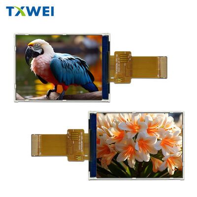
2.4 Inch 240x320 IPS TFT LCD Module 8-Bit MCU Parallel 4-Line SPI Interface 26 Pin

2.4 Inch 240x320 IPS TFT LCD Module 8-Bit MCU Parallel 4-Line SPI Interface 26 Pin

MOQ: Sample order accepted, 100 pcs
Price: Negotiable
Standard Packaging: Anti-static bag, foam, export carton
Delivery Period: 15-25 working days after sample approval
Payment Method: T/T,L/C,D/P
Supply Capacity: 10,000 pcs per month
Detail Information
Place of Origin
Guangdong, China
Brand Name
TXWEI
Certification
CE, RoHS, FCC
Model Number
TXW240082B0
Size:
2.4 Inch
Display Type:
IPS TFT, Transmissive, Normally Black
Resolution:
240 X RGB X 320 Dots
Driver IC:
Sitronix ST7789V2-G4-A
Interface:
8-bit MCU Parallel (8080) Or 4-line SPI, Selected By S/P Pin
Pixel Pitch:
0.153 X 0.153 Mm
Active Area:
36.72 X 48.96 Mm
Outline Size:
42.72 X 58.65 X 2.35 Mm
FPC:
26 Pin With Stiffener
Viewing Direction:
All Clock
Uniformity:
80% Minimum
Colors:
65K / 262K Selectable
Backlight:
4 White LEDs, 80 MA, 2.8-3.2 V, 30,000 Hours
I/O Voltage:
IOVCC 1.65-3.3 V, VCI 2.7-3.3 V
Operating Temperature:
-20 To +60 C
Storage Temperature:
-30 To +70 C
Touch:
None
Highlight:

2.4 Inch IPS TFT LCD

,

240x320 TFT LCD Module

,

8-Bit MCU Parallel SPI LCD

Product Description
Selection Worksheet  /  TXW240082B0
Eight Data Lines Are Usually Enough
A 2.4-inch IPS panel with an 8080-style 8-bit MCU bus and a 4-line serial option, selected by one pin. Written as the six questions a hardware team actually asks in a design review.
240 x 320  IPS
8-bit  MCU parallel
4-line  SPI option
2.35 mm  module
3 V  backlight

There is a moment in every small-display project when the schematic gets opened for the last time before tooling, and someone counts the pins left on the microcontroller. It is rarely a comfortable count. The display wants a bus, the keypad wants six lines, the sensor has an interrupt, the radio occupies the serial port, and the debug header has already been sacrificed. Designs do not fail here because the panel was not bright enough; they fail because the panel wanted twenty-two wires and there were nine.

This module is the answer to that particular afternoon. It carries an 8080-style 8-bit MCU interface — eight data lines plus chip select, register select, write and read — and a four-line serial interface, with a single pin deciding which of the two the controller sees. No bridge, no external timing generator, no second voltage rail to sequence. The six questions below are the ones worth answering before the layout is signed off.

Q1
What does the S/P pin actually do?
It tells the controller which dialect to speak. Held low, the panel expects the parallel MCU bus: DB0 to DB7 carry data, CS selects the chip, RS distinguishes command from data, WR strobes a write and RD strobes a read. Held high, the same pins are reinterpreted as a four-line serial port — clock, chip select, data in and a data/command line. The choice is made in copper, not in firmware, so it has to be decided at schematic capture rather than during bring-up.
Q2
Why keep an 8-bit bus in an era of RGB panels?
Because an 8-bit bus is a memory-mapped window. On parts like the ST7789V2 family the controller sees the panel as an address, and a byte written to that address becomes a pixel — no frame buffer, no DMA descriptor chain, no display refresh engine. For a product whose interface changes a digit every second, that is the cheapest possible architecture: no RAM budget, no bus bandwidth, no tearing logic. The 8080 protocol has survived since the 1970s for exactly this reason.
Q3
Does the panel support reading back?
Yes, and that is rarer than it should be at this size. RD is brought out on the tail, so the controller can read the display data RAM as well as write it. Teams use it for self-tests on the production line: write a known pattern, read it back, and the fixture confirms both the panel and the flex in a single step rather than relying on a human looking at a screen.
Q4
What about brightness?
This build is specified with uniformity at 80 percent minimum and brightness confirmed by measurement on the sample rather than fixed as a printed figure at drawing stage. That is a deliberate arrangement rather than an omission: it lets the same structure serve different backlight builds. Ask for the measured value with your sample, and the quotation will carry the number that applies to your order.
Q5
How much power does it really take?
Four white LEDs at 80 milliamps on a 2.8 to 3.2 volt string — under a quarter of a watt of backlight, driven directly from the logic rail through a limiting element. Logic runs on VCI from 2.7 to 3.3 volts, and the I/O rail accepts anything from 1.65 to 3.3 volts, so a 1.8 volt host and a 3.3 volt host use the same panel without level shifters.
Q6
What will not fit?
The active area is 36.72 by 48.96 millimetres and the module is 42.72 by 58.65 by 2.35 millimetres, with a 26-pin tail and a stiffener. If the enclosure seat was drawn for a 2.8-inch part, this one will not fill it — the outline is four millimetres narrower and the image is smaller. Moving down from 2.8 to 2.4 inches is a mechanical decision first and a display decision second.

The two dialects side by side

Signal group S/P low — 8-bit MCU S/P high — 4-line serial
DataDB0 to DB7SPI-SDA, bidirectional
Clock and strobesWR and RDSPI-SCL only
Command selectRS pinSPI-RS pin
Typical host8-bit MCU with an external memory busAny MCU with four spare pins

Three mistakes that cost a week each

The first is choosing the serial mode on a product that repaints its whole screen. Serial is comfortable for a value that changes once a second; it becomes a visible sweep when the UI swaps pages, and by then the board is in tooling. The second is forgetting that an 8-bit MCU bus is not free: the address window has to be decoded, and on some parts the write strobe needs a wait state configured, which is invisible until the first photographically black screen appears. The third is mechanical, not electrical — a 26-pin tail with a stiffener behaves differently from a bare flex, and a housing that pinched the cable at assembly will fail in the field, not in the lab.

None of these are exotic. All three are cheap to avoid in a design review and expensive to find later, which is the reason this page is written as a set of questions instead of a feature list.

A typical first day, in order
Hour one  —  power the VCI rail, hold RESET low, release, and confirm the panel draws nothing unexpected.
Hour two  —  send the initialisation sequence from the datasheet over whichever dialect the board was laid out for.
Hour three  —  fill the screen with one colour; if it appears, the timing and the mode agree.
Hour four  —  write a test pattern, read it back through RD, and record the result for the production fixture.

Bring this list to the design review

Pre-layout checks
☐  Count the pins before choosing the mode — S/P is a copper decision.
☐  Confirm the seat depth: 2.35 mm module with a stiffened tail.
☐  Confirm the I/O rail: 1.65 to 3.3 V, no shifter required.
☐  Confirm the backlight path: 3 V string, current limited, no boost.
☐  Ask for the measured brightness with the sample, in writing.
⛔  Do not plan an outdoor product: operating range is -20 to +60 °C.

Where a 2.4-inch numeric panel still wins

Four product families account for most of this panel's volume, and they share one trait: the screen is a readout, not an experience. A benchtop power supply or a signal generator where the interface is a voltage, a current and a limit indicator. A battery or fuel gauge where the only thing that changes is a number and a bar. A heating controller with a set-point and three status icons. A portable tester where the operator glances, reads and moves on. In each case a frame buffer would be dead weight: the host has 32 kilobytes of RAM, and paying for a display engine to avoid using eight wires is the wrong trade.

Benchtop instruments
Set-point, reading and a limit alarm. Menu depth of two. Redrawn only when a key is pressed.
Portable testers
Held in one hand, read in a second, put away. Battery life matters more than refresh rate.
Controllers and thermostats
Fixed layout, occasional change, long service life. The panel outlives three firmware generations.
Legacy platform refreshes
An existing 8-bit design that needs a colour screen without a new processor, toolchain or RTOS.

The cost argument deserves to be stated plainly, because it is usually the real reason a project is looking at this category. Moving to a host with a display engine means a new microcontroller, a new toolchain, a new memory budget and a new validation cycle — months of engineering to save a handful of GPIO. Staying with the 8-bit bus means the existing firmware keeps its structure and the display becomes a peripheral rather than an architecture. On a product where the display is ten percent of the value, that is not a compromise. It is the correct engineering decision, and it is why this interface is still specified in 2026.

What this part is not

There is no RGB bus here, so a design that needs a hardware refresh engine with a big frame buffer should look at our 2.4-inch dual-interface module instead — same glass size, different connectivity. There is no touch layer in the stack and no bonded option on this build. And 240 by 320 is a numeric interface: text, numbers, bars, icons. It is not a panel for photographs or video, and it does not pretend to be.

Reliability and delivery — 96 hours storage at +70 and -30 °C, 96 hours operating at +60 and -20 °C, 96 hours at 50 °C and 90 percent RH, ten thermal shock cycles between -20 and +60 °C. Samples ship with timing notes for both interface modes; customization covers FPC length, pinout, cable assembly and front treatment; production runs 15 to 25 working days after approval, 10,000 pieces per month, packed in anti-static bags with foam in export cartons.

Two more questions, briefly

Can I run 65K colour instead of 262K?
Yes, selected in software. 65K halves the bytes per pixel, which on an 8-bit bus is the difference between a comfortable refresh and a slow one.
Is there a viewing-angle surprise?
The panel is specified with a free viewing direction and is an IPS build, so the image stays consistent off-axis — which matters when a bench instrument is read from the side by a second person.

A last note on how to read this page. Nothing here is a claim about being the best panel of its size. It is a description of one specific shape of product — eight wires, no frame buffer, 2.35 millimetres, indoor use — and a list of the questions that decide whether that shape fits. If it does, the rest is drawing work. If it does not, the honest answer is a different module, and we will say so before a purchase order exists.

Send the pin count and the host part number.

Two pieces of information decide everything else on a panel this size. What comes back is a drawing, a timing note for the mode you chose, a measured brightness figure and a quotation.

TXW240082B0  ·  TXWEI  ·  Shenzhen, Guangdong, China  ·  RoHS compliant

Products
PRODUCTS DETAILS
2.4 Inch 240x320 IPS TFT LCD Module 8-Bit MCU Parallel 4-Line SPI Interface 26 Pin
MOQ: Sample order accepted, 100 pcs
Price: Negotiable
Standard Packaging: Anti-static bag, foam, export carton
Delivery Period: 15-25 working days after sample approval
Payment Method: T/T,L/C,D/P
Supply Capacity: 10,000 pcs per month
Detail Information
Place of Origin
Guangdong, China
Brand Name
TXWEI
Certification
CE, RoHS, FCC
Model Number
TXW240082B0
Size:
2.4 Inch
Display Type:
IPS TFT, Transmissive, Normally Black
Resolution:
240 X RGB X 320 Dots
Driver IC:
Sitronix ST7789V2-G4-A
Interface:
8-bit MCU Parallel (8080) Or 4-line SPI, Selected By S/P Pin
Pixel Pitch:
0.153 X 0.153 Mm
Active Area:
36.72 X 48.96 Mm
Outline Size:
42.72 X 58.65 X 2.35 Mm
FPC:
26 Pin With Stiffener
Viewing Direction:
All Clock
Uniformity:
80% Minimum
Colors:
65K / 262K Selectable
Backlight:
4 White LEDs, 80 MA, 2.8-3.2 V, 30,000 Hours
I/O Voltage:
IOVCC 1.65-3.3 V, VCI 2.7-3.3 V
Operating Temperature:
-20 To +60 C
Storage Temperature:
-30 To +70 C
Touch:
None
Minimum Order Quantity:
Sample order accepted, 100 pcs
Price:
Negotiable
Packaging Details:
Anti-static bag, foam, export carton
Delivery Time:
15-25 working days after sample approval
Payment Terms:
T/T,L/C,D/P
Supply Ability:
10,000 pcs per month
Highlight

2.4 Inch IPS TFT LCD

,

240x320 TFT LCD Module

,

8-Bit MCU Parallel SPI LCD

Product Description
Selection Worksheet  /  TXW240082B0
Eight Data Lines Are Usually Enough
A 2.4-inch IPS panel with an 8080-style 8-bit MCU bus and a 4-line serial option, selected by one pin. Written as the six questions a hardware team actually asks in a design review.
240 x 320  IPS
8-bit  MCU parallel
4-line  SPI option
2.35 mm  module
3 V  backlight

There is a moment in every small-display project when the schematic gets opened for the last time before tooling, and someone counts the pins left on the microcontroller. It is rarely a comfortable count. The display wants a bus, the keypad wants six lines, the sensor has an interrupt, the radio occupies the serial port, and the debug header has already been sacrificed. Designs do not fail here because the panel was not bright enough; they fail because the panel wanted twenty-two wires and there were nine.

This module is the answer to that particular afternoon. It carries an 8080-style 8-bit MCU interface — eight data lines plus chip select, register select, write and read — and a four-line serial interface, with a single pin deciding which of the two the controller sees. No bridge, no external timing generator, no second voltage rail to sequence. The six questions below are the ones worth answering before the layout is signed off.

Q1
What does the S/P pin actually do?
It tells the controller which dialect to speak. Held low, the panel expects the parallel MCU bus: DB0 to DB7 carry data, CS selects the chip, RS distinguishes command from data, WR strobes a write and RD strobes a read. Held high, the same pins are reinterpreted as a four-line serial port — clock, chip select, data in and a data/command line. The choice is made in copper, not in firmware, so it has to be decided at schematic capture rather than during bring-up.
Q2
Why keep an 8-bit bus in an era of RGB panels?
Because an 8-bit bus is a memory-mapped window. On parts like the ST7789V2 family the controller sees the panel as an address, and a byte written to that address becomes a pixel — no frame buffer, no DMA descriptor chain, no display refresh engine. For a product whose interface changes a digit every second, that is the cheapest possible architecture: no RAM budget, no bus bandwidth, no tearing logic. The 8080 protocol has survived since the 1970s for exactly this reason.
Q3
Does the panel support reading back?
Yes, and that is rarer than it should be at this size. RD is brought out on the tail, so the controller can read the display data RAM as well as write it. Teams use it for self-tests on the production line: write a known pattern, read it back, and the fixture confirms both the panel and the flex in a single step rather than relying on a human looking at a screen.
Q4
What about brightness?
This build is specified with uniformity at 80 percent minimum and brightness confirmed by measurement on the sample rather than fixed as a printed figure at drawing stage. That is a deliberate arrangement rather than an omission: it lets the same structure serve different backlight builds. Ask for the measured value with your sample, and the quotation will carry the number that applies to your order.
Q5
How much power does it really take?
Four white LEDs at 80 milliamps on a 2.8 to 3.2 volt string — under a quarter of a watt of backlight, driven directly from the logic rail through a limiting element. Logic runs on VCI from 2.7 to 3.3 volts, and the I/O rail accepts anything from 1.65 to 3.3 volts, so a 1.8 volt host and a 3.3 volt host use the same panel without level shifters.
Q6
What will not fit?
The active area is 36.72 by 48.96 millimetres and the module is 42.72 by 58.65 by 2.35 millimetres, with a 26-pin tail and a stiffener. If the enclosure seat was drawn for a 2.8-inch part, this one will not fill it — the outline is four millimetres narrower and the image is smaller. Moving down from 2.8 to 2.4 inches is a mechanical decision first and a display decision second.

The two dialects side by side

Signal group S/P low — 8-bit MCU S/P high — 4-line serial
DataDB0 to DB7SPI-SDA, bidirectional
Clock and strobesWR and RDSPI-SCL only
Command selectRS pinSPI-RS pin
Typical host8-bit MCU with an external memory busAny MCU with four spare pins

Three mistakes that cost a week each

The first is choosing the serial mode on a product that repaints its whole screen. Serial is comfortable for a value that changes once a second; it becomes a visible sweep when the UI swaps pages, and by then the board is in tooling. The second is forgetting that an 8-bit MCU bus is not free: the address window has to be decoded, and on some parts the write strobe needs a wait state configured, which is invisible until the first photographically black screen appears. The third is mechanical, not electrical — a 26-pin tail with a stiffener behaves differently from a bare flex, and a housing that pinched the cable at assembly will fail in the field, not in the lab.

None of these are exotic. All three are cheap to avoid in a design review and expensive to find later, which is the reason this page is written as a set of questions instead of a feature list.

A typical first day, in order
Hour one  —  power the VCI rail, hold RESET low, release, and confirm the panel draws nothing unexpected.
Hour two  —  send the initialisation sequence from the datasheet over whichever dialect the board was laid out for.
Hour three  —  fill the screen with one colour; if it appears, the timing and the mode agree.
Hour four  —  write a test pattern, read it back through RD, and record the result for the production fixture.

Bring this list to the design review

Pre-layout checks
☐  Count the pins before choosing the mode — S/P is a copper decision.
☐  Confirm the seat depth: 2.35 mm module with a stiffened tail.
☐  Confirm the I/O rail: 1.65 to 3.3 V, no shifter required.
☐  Confirm the backlight path: 3 V string, current limited, no boost.
☐  Ask for the measured brightness with the sample, in writing.
⛔  Do not plan an outdoor product: operating range is -20 to +60 °C.

Where a 2.4-inch numeric panel still wins

Four product families account for most of this panel's volume, and they share one trait: the screen is a readout, not an experience. A benchtop power supply or a signal generator where the interface is a voltage, a current and a limit indicator. A battery or fuel gauge where the only thing that changes is a number and a bar. A heating controller with a set-point and three status icons. A portable tester where the operator glances, reads and moves on. In each case a frame buffer would be dead weight: the host has 32 kilobytes of RAM, and paying for a display engine to avoid using eight wires is the wrong trade.

Benchtop instruments
Set-point, reading and a limit alarm. Menu depth of two. Redrawn only when a key is pressed.
Portable testers
Held in one hand, read in a second, put away. Battery life matters more than refresh rate.
Controllers and thermostats
Fixed layout, occasional change, long service life. The panel outlives three firmware generations.
Legacy platform refreshes
An existing 8-bit design that needs a colour screen without a new processor, toolchain or RTOS.

The cost argument deserves to be stated plainly, because it is usually the real reason a project is looking at this category. Moving to a host with a display engine means a new microcontroller, a new toolchain, a new memory budget and a new validation cycle — months of engineering to save a handful of GPIO. Staying with the 8-bit bus means the existing firmware keeps its structure and the display becomes a peripheral rather than an architecture. On a product where the display is ten percent of the value, that is not a compromise. It is the correct engineering decision, and it is why this interface is still specified in 2026.

What this part is not

There is no RGB bus here, so a design that needs a hardware refresh engine with a big frame buffer should look at our 2.4-inch dual-interface module instead — same glass size, different connectivity. There is no touch layer in the stack and no bonded option on this build. And 240 by 320 is a numeric interface: text, numbers, bars, icons. It is not a panel for photographs or video, and it does not pretend to be.

Reliability and delivery — 96 hours storage at +70 and -30 °C, 96 hours operating at +60 and -20 °C, 96 hours at 50 °C and 90 percent RH, ten thermal shock cycles between -20 and +60 °C. Samples ship with timing notes for both interface modes; customization covers FPC length, pinout, cable assembly and front treatment; production runs 15 to 25 working days after approval, 10,000 pieces per month, packed in anti-static bags with foam in export cartons.

Two more questions, briefly

Can I run 65K colour instead of 262K?
Yes, selected in software. 65K halves the bytes per pixel, which on an 8-bit bus is the difference between a comfortable refresh and a slow one.
Is there a viewing-angle surprise?
The panel is specified with a free viewing direction and is an IPS build, so the image stays consistent off-axis — which matters when a bench instrument is read from the side by a second person.

A last note on how to read this page. Nothing here is a claim about being the best panel of its size. It is a description of one specific shape of product — eight wires, no frame buffer, 2.35 millimetres, indoor use — and a list of the questions that decide whether that shape fits. If it does, the rest is drawing work. If it does not, the honest answer is a different module, and we will say so before a purchase order exists.

Send the pin count and the host part number.

Two pieces of information decide everything else on a panel this size. What comes back is a drawing, a timing note for the mode you chose, a measured brightness figure and a quotation.

TXW240082B0  ·  TXWEI  ·  Shenzhen, Guangdong, China  ·  RoHS compliant

sitemap |  Privacy Policy | China Good Quality TFT LCD Display Supplier. Copyright © 2024-2026 Shenzhen Tianxianwei Technology Co., Ltd. . All Rights Reserved.